
29 May 2026
For anyone building a platform that has to know where it is at all times, whether that platform is an autonomous vehicle, a survey vessel, an industrial robot, or an airborne mapping sensor, GNSS alone is rarely enough. Satellite signals drop inside tunnels, under dense canopy, between high-rise buildings, and in any environment where the sky is partially blocked. That is where an inertial navigation system steps in. An INS does not need external signals to work. It tracks movement using its own motion sensors, which is what makes it indispensable anywhere continuous positioning matters. This guide walks through what an INS is, how an IMU produces the measurements at its core, why drift is the central challenge, and how GNSS/INS integration turns two imperfect technologies into a single reliable solution.
An inertial navigation system, commonly shortened to INS, is a self-contained navigation solution that calculates position, velocity, and attitude by measuring the platform's own motion. It has three essential ingredients: a sensor package, a processing unit, and a set of algorithms that take raw motion measurements and turn them into a continuously updated navigation state. The name "inertial" comes from Newton's first law. The system observes how forces acting on the platform change its motion and works backward from those observations to reconstruct where the platform is and how it is oriented.
Crucially, an INS does not require any information from outside the vehicle. No satellite signal, no radio beacon, no camera, no map. Everything the system needs is produced by the sensors inside it. That independence is the feature that makes inertial navigation irreplaceable for subsea autonomous vehicles, autonomous mining equipment underground, long-tunnel rail and road inspection rigs, and any industrial or commercial platform that occasionally loses contact with GNSS.
At the heart of every INS sits an inertial measurement unit, or IMU. An IMU combines three-axis accelerometers and three-axis gyroscopes in a rigid package. The accelerometers measure the specific force acting on the platform along three orthogonal axes. The gyroscopes measure the rate of rotation around those same axes, in roll, pitch, and yaw. Together the two sensor sets describe six degrees of freedom, which is exactly what is needed to reconstruct full three-dimensional motion.
Getting from raw IMU data to a useful position takes mathematical integration. Rotation rates are integrated once to produce attitude. Accelerometer outputs, once gravity and platform tilt have been removed, are integrated once to produce velocity and a second time to produce position. This process is called strapdown inertial navigation, and the word "dead reckoning" is often used to describe it. The system has a known starting point and keeps updating where it is by continuously measuring how it has moved from that reference.
Because every step of integration compounds small measurement errors, INS accuracy is a function of two things: how good the IMU is and how recently the solution was corrected against a known truth. A high-precision IMU installed in a survey aircraft behaves very differently from a consumer MEMS IMU in a smartphone. Both are inertial, but the bias, noise, and drift characteristics of the sensors differ by several orders of magnitude.
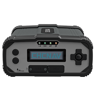
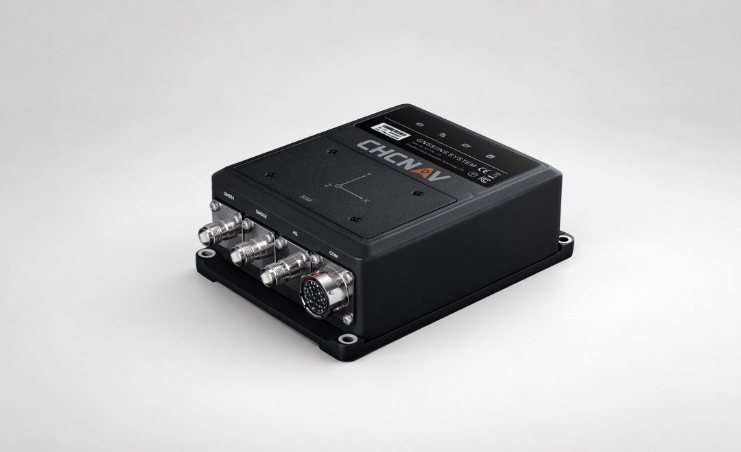
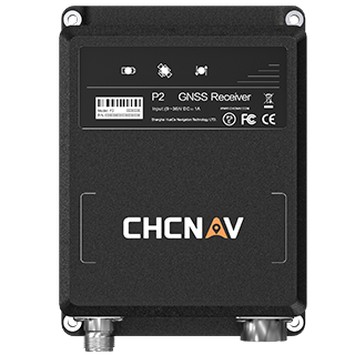
These integration principles are implemented in professional GNSS/INS systems that combine multi-constellation GNSS with an industrial-grade MEMS IMU to deliver continuous positioning, attitude, and velocity output. The CGI-610 is one example of such a system, shown below.
Inertial navigation offers several practical advantages that no other positioning technology can match on its own.
These benefits are why an INS navigation system sits at the core of high-value platforms in autonomy, mapping, and industrial control, even when GNSS is also available.
To understand INS performance, it helps to understand the sensors themselves. An IMU sensor package contains two distinct measurement families, each with its own error characteristics.
Accelerometers measure specific force along a single axis. In a stationary IMU sitting on a table, each accelerometer's output is dominated by the component of gravity acting along that axis. Subtract gravity, and whatever remains is the acceleration of the platform itself. The main error sources are bias, which is a slowly changing offset; scale factor error, which changes the gain of the measurement; and noise, which is high-frequency randomness that limits how quickly small motions can be detected.
Gyroscopes measure angular rate, or how fast the platform is rotating around a given axis. Their errors follow the same families: bias, scale factor, and noise. Gyroscope bias is particularly important because its integral builds up as a heading error over time, and heading error in turn corrupts the orientation of every subsequent accelerometer measurement. A bad gyro degrades the whole solution.
MEMS IMU devices, which use micro-electromechanical silicon structures, have become the workhorse of modern inertial navigation. They are small, low-power, and inexpensive enough to include in consumer products. Performance has improved dramatically over the last decade, to the point that a high-grade MEMS IMU can now meet the requirements of survey platforms, industrial navigation, and autonomous driving research. The tradeoff is that MEMS sensors still drift faster than fibre-optic or ring-laser gyroscopes, which is why they are almost always paired with GNSS or another aiding source in professional systems.
The single most important concept in inertial navigation is drift. A standalone INS, left to its own devices, will produce a position estimate that slowly wanders away from the true location. The rate of that drift is the headline specification for any inertial unit, and it varies by orders of magnitude across product tiers.
A consumer-grade MEMS IMU in a smartphone might drift several metres within a few seconds of GNSS loss. A survey-grade MEMS IMU with careful calibration might hold sub-metre accuracy for tens of seconds of GNSS outage. A high-precision IMU can hold sub-metre accuracy for many minutes. A navigation-grade unit using fibre-optic gyroscopes can deliver performance sufficient for subsea survey vessels and long-endurance airborne mapping platforms. The physics are the same, only the sensor quality changes.
Every IMU specification implies an unspoken assumption: drift is measured from the last known good reference. That is why almost every real-world inertial system is not just an INS, but an aided INS. GNSS, a visual odometer, a wheel encoder, a Doppler velocity log, or any other external measurement is fused with the inertial solution to pull it back toward the truth before drift accumulates. The choice of aiding source is what distinguishes product categories. In the geospatial and automotive domains, the overwhelmingly common choice is GNSS, and the combination has a name of its own.
A GNSS/INS system, also called a GNSS-aided INS, is the practical answer to both technologies' limitations. GNSS provides absolute positioning that does not drift but depends on satellite visibility. INS provides continuous short-term accuracy without any external signal. Fuse the two and the result is a system that is better than either alone, with none of the individual weaknesses showing through to the user.
The fusion itself is handled by a Kalman filter, which continuously estimates the IMU's bias, scale factor, and attitude errors using GNSS observations as the truth reference. When GNSS is available, the filter calibrates the IMU and the system publishes a tight, GNSS-quality position. When GNSS is lost, the filter stops receiving new corrections but the IMU continues to propagate the solution forward. Because the IMU was recently calibrated, drift during the outage is bounded. When GNSS returns, the filter reacquires and resets any accumulated error.
The benefit is visible in real deployments. A car driving into an urban canyon keeps a smooth lane-level position instead of jumping between buildings. A survey USV entering the shadow of a bridge holds its trackline instead of flagging data as unreliable. A UAV photogrammetry flight continues to produce georeferenced imagery through a brief GNSS dropout, with no visible seam in the final orthomosaic. In each case, the INS fills a gap that GNSS alone would leave empty.
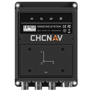
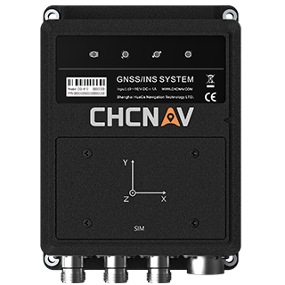
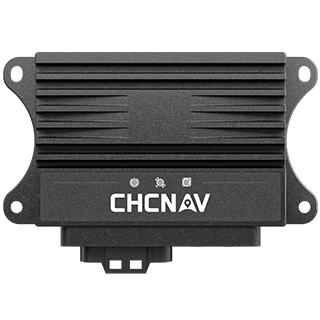
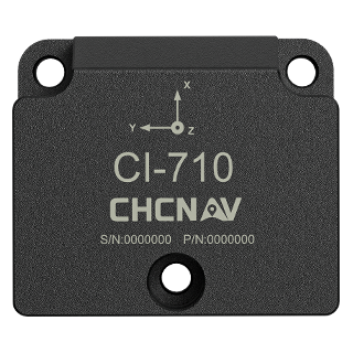
CHC Navigation's CGI-610 dual-antenna GNSS/INS, CGI-830 GNSS/IMU ground truth unit, and CI-710 high-precision MEMS IMU are all built around this principle. Readers who want a deeper look at the fusion benefits can also read the companion piece on GNSS-INS integration.
When evaluating an inertial solution, the grade of the IMU is usually the first decision. Modern options fall into a rough hierarchy based on the drift rate of the gyroscopes, which is the dominant factor in medium-to-long-term accuracy.
The right choice depends on how long the system must operate without GNSS aiding, how demanding the attitude accuracy requirement is, and how much size, weight, and power the host platform can absorb. For most commercial geospatial and autonomy applications in 2026, a high-precision MEMS IMU tightly coupled with a multi-frequency GNSS receiver is the balance that wins.
Inertial navigation sits quietly inside a surprising number of industries. Some of the most common applications include:
An inertial navigation system is one of the few technologies that can keep producing a trustworthy position when the rest of the world goes dark. The secret is the IMU at its core, a compact sensor package that measures the platform's own motion fast enough and accurately enough to keep navigation continuous between external corrections. On its own, any INS eventually drifts. Paired with GNSS, it becomes the foundation of modern positioning across autonomy, geospatial, marine, and airborne applications. Whether the starting point is a simple question like "what is an IMU sensor" or a detailed trade study between MEMS and fibre-optic INS, the underlying principles are the same, and the engineering choices all come down to managing drift and choosing the right aiding strategy for the job.
CHC Navigation (CHCNAV) develops advanced mapping, navigation, and positioning solutions designed to increase productivity and efficiency. Serving industries such as geospatial, agriculture, machine control and autonomy, CHCNAV delivers innovative technologies that empower professionals and drive industry advancement. With a global presence spanning over 140 countries and a team of more than 2,200 professionals, CHC Navigation is recognized as a leader in the geospatial industry and beyond. For more information about CHC Navigation [Huace:300627.SZ], please visit: https://navigation.chcnav.com/about/overview
Have a question about our solutions or dealership opportunities?